The steel beam is shaped and cut to suit.
Chapter 2: Boyhood
If you are a structural engineer you probably don’t want to read an architect’s raving around the boyhood of a steel beam, I this case I would suggest you to stand up and perhaps enjoy a walk in the park.
This is the continuation of the story of my trip in a steel mill to follow the journey of a beam from her non-defined liquid form to the final product installed in a building in the City of London.
We left the first chapter when I and the engineers were looking at the big steel plates just rolled, cooled and cut, still slightly hot from the furnace yet and piled outside, ready to be moved to another facility to be refined and treated.
A steel tailor’s shop
The day after we were all in another facility in the Yorkshire, surely the environment appeared radically different from the steel mill: not anymore the Vulcan’s forge with raw materials and lava.
It was rather a sort of tailor’s shop but bigger and noisier of course, dedicated to the forming, shaping, cutting, welding and final dressing of the beam.
The cutting of the steel beam
First of all our big plates went under the care of a powerful laser cut who subdivided them in linear plates, destined to be, depending on their thickness, flanges or web.
Usually the web plates are wider but thinner and the two flanges are thicker instead to maximize the structural efficiency of the beam.
Some of the plates, the one destined to be the web, as I noticed, were not cut straight but slightly curved instead. An engineer explained to me that the curve wasn’t a mistake but it was done on purpose and specifically designed in that way.
The reason is that the beam, once installed, has a good chance to deflect under the pressure of dead and live loads and the curve of the web is in fact in the opposite direction of the deflection. The intent is that, hopefully, the deflected beam will be horizontal again once loaded on site (the engineers didn’t sound so sure about this).
At this point we all followed some of the thinner plates (the webs), moved by rolls, going toward another fascinating machine.
One of the many advantages of using the structural steel in buildings is that the web can be perforated, this allows for the service’s ducts, pipes and cables to run within the structural zone in the holes. Sharing the same area is a way to optimise the use of space. In this way it is possible to reduce drastically the total thickness of the horizontal structure in comparison with the use of concrete or other technologies.
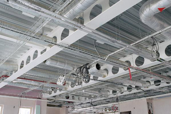
Showing complex services integration in cellular, long-span beams, Bishop Aukland Hospital
(Image courtesy of of ASD Westok Ltd.)
The mysterious machine we were approaching was, in fact, a big cad-controlled laser cut cutting out the necessary holes as requested by the M&E engineers.
Suddenly it became clear to me why structural engineers don’t get together so easily with M&E engineers: the second ones perforate the structure so lovingly designed by the first ones!
At this point I and my friend engineers all moved following our now shaped and cut webs and flanges in their heroic advance toward another noisy, flamboyant area dedicated to one of the most interesting phases: the assembling of the main three parts of the body of the beams into an individual H section.
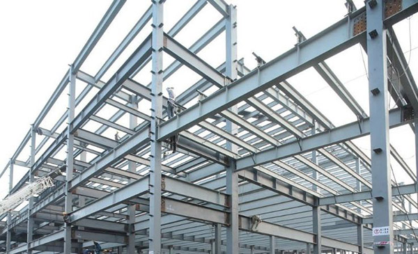
Hot rolled structural steel H beams
The sewing – Gas metal arc welding
There are several ways to weld, and I need here to refer to the introduction we had from the gentle guide even if the tone will become a bit educational.
What we know as welding in structural steel means to fuse together two parts of similar or identical steel by melting or plastic deformation of the joint area. Usually but not always this is achieved with the addition of further material (filler).
The two main categories of welding for steelwork are fusion welding and pressure welding (which doesn’t necessarily require the addition of filler)
There are many different welding processes and the differences are mainly in the way the welding is protected against the ingress of oxygen or other impurities which can compromise the quality of the welding.
For our specific beam the process used was the gas metal arc welding (GMAW) wherein the weld pool is protected by a gas fed directly to the weld.
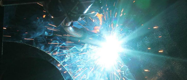
Showing the process of Gas metal arc welding being carried out by Veem Ltd, Australia
What we could see from our position of steel tourists was actually a curious, not too big, and relatively silent machine running as a snail along the beam. The two flanges and the web were kept together under pressure (with hydraulic driven arms) and this mechanical robotic snail was leaving behind his passage a sparkling slime: that snail’s track was the welding.
All the area was quite noisy with plenty of the traditional welding’s sparks because many details which are necessary to complete the fabrication of structural and architectural metalwork are still done by hand with more traditional arc welding tools.
After the intervention of the automatic welder (the snail) our beam was cut once again to her precise length by a cutting disc and then she was finally, amazingly, there, all formed and only a few steps from her entry into society.